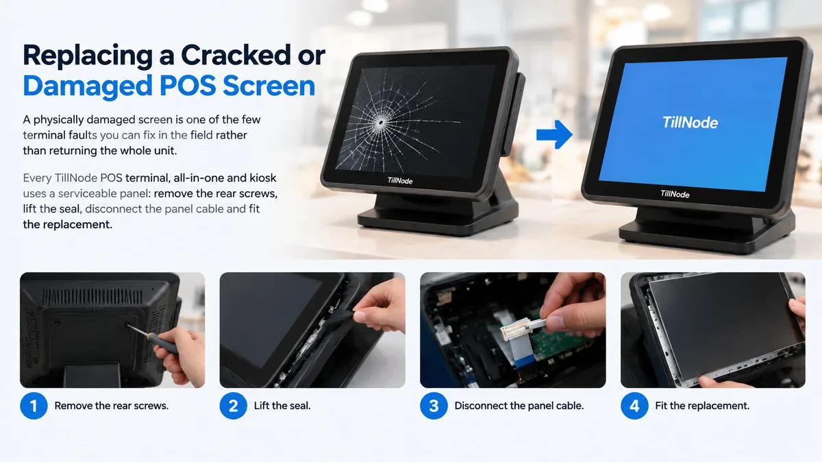
Replacing a Cracked or
Damaged POS Screen
A physically damaged screen is one of the few terminal faults you can fix in the field rather than returning the whole unit. Every TillNode POS terminal, all-in-one and kiosk uses a serviceable panel: remove the rear screws, lift the seal, disconnect the panel cable and fit the replacement. If the glass is intact and only the touch layer has failed, work through replacing the touch screen instead, and the rest of the set sits in the troubleshooting index.
Is the Screen Actually Faulty?
Before opening anything, confirm the panel itself is the failure. A “black screen” is frequently a cable, a backlight or a software problem — and in those cases a replacement panel fixes nothing, at the cost of a screen that was still working.
| What you see | Replace the panel? | Correct action |
|---|---|---|
| Cracked glass, star fracture or spider-web | Yes — physical damage | Continue with this guide |
| Liquid crystal bleed, dark blotch spreading | Yes — panel damage | Continue with this guide |
| Permanent bright or dark vertical lines | Yes — panel or driver | Continue with this guide |
| Backlight visible with a torch, but no image | No — panel is alive | See black screen diagnosis |
| No backlight, torch shows nothing | Maybe — LCD or power | Diagnose first, then return |
| Image fine but touch does nothing | No — not an LCD fault | See touch screen guide |
| Image fine but touch offset or drifting | No — calibration | See touch screen guide |
| Flickers only when the bezel is pressed | No — loose cable | Reseat the cable first |
| Displays only in the boot menu | No — software or driver | See black screen diagnosis |
The torch test
In a darkened room, shine a torch at the screen at a shallow angle.
- · Faint content visible — the panel hardware works. Do not replace the screen.
- · Completely dark — the panel or its supply is implicated.
Ordering the right panel
Replacement panels are model-specific — they are not interchangeable between terminals. You do not need to measure the screen or quote a resolution.
Simply quote your POS terminal or kiosk model number when ordering, and we will supply the matching panel.
Panel Specifications by Size
Ordering is by model number, but the table below is what you check the arriving panel against. If the interface or the pin count does not match, do not fit it.
| Screen size | Interface | Pins | Resolution |
|---|---|---|---|
| 10.1″ | LVDS | 40 pin | 1280 × 800 |
| 11.6″ | eDP | 30 pin | 1366 × 768 |
| 15″ | LVDS | 30 pin | 1024 × 768 |
| 15.6″ | eDP | 30 pin | 1366 × 768 |
| 21.5″ | eDP | 30 pin | 1920 × 1080 |
| 27″ | eDP | 30 pin | 1920 × 1080 |
Every panel in the range uses a 30-pin connector except the 10.1-inch, which is 40-pin. Panels from 21.5-inch upwards — including kiosk and all-in-one displays — are eDP, while the smaller sizes mix eDP and LVDS. eDP and LVDS are not interchangeable, so check the interface column against the panel you received. 4K resolutions are available on 21.5-inch and larger panels.
Bonded displays: what you are actually replacing
On the P-series (SN-P10, P20, P30, P60 and P90) and on kiosks, the touch layer is laminated directly to the LCD. There is no separate touch layer to lift, so the display is replaced as a complete assembly rather than as a bare panel.
The eleven entry-level models — SN-A10, A15, B10, B20, B30, C10, C20, C30, F10, F20 and W50 — use a non-bonded stack, so the LCD and the touch layer can be replaced independently. Check which group your model falls into before ordering.
Before You Start
This is a field-serviceable repair, but it is not a casual one. Preparation takes ten minutes and is what separates a clean swap from a cracked replacement panel.
What you will need
- ✓ Correct replacement panel for your exact model
- ✓ Fresh sealing strip — the old one cannot be reused
- ✓ Plastic spudgers — never metal
- ✓ A screwdriver set matched to the casing screws
- ✓ Anti-static wrist strap
- ✓ Isopropyl alcohol and lint-free cloth
- ✓ A soft mat or cloth to rest the panel on
Four rules before you begin
- 1. Disconnect power and hold the power button for five seconds to discharge residual current. LCD driver circuits carry high voltage.
- 2. Wear an anti-static strap. Static discharge destroys LCD driver boards.
- 3. Back up the terminal if you will power it up to test afterwards. A screen swap is a good moment for a routine backup.
- 4. Photograph everything first — screw positions, cable routing and the seal shape. Reassembly depends entirely on these images.
A note on panel variants: on some models the touch layer is bonded directly to the LCD with optical adhesive. Where this is the case the touch layer cannot be separated, and the complete display assembly is replaced instead. If the touch layer resists separation at the edge, stop and contact your supplier before applying more force.
Replacing the LCD Panel, Step by Step
Seven stages, from removing the rear screws to closing the casing. Work slowly at each cable — the panel itself is robust, but the ribbon connectors are not.
Remove the rear screws
Place the terminal face-down on a soft cloth to protect the panel. Remove the screws securing the rear casing or the display assembly.
Screws on the same unit are often not uniform — lengths and thread types can differ by position. Lay them out in order as you remove them. A long screw driven into a short hole will push through the panel from behind.
Lift the rear casing
Work a plastic spudger into the seam and release the casing gradually. Start at one corner, move to the next once you hear the clip release, and avoid levering a whole edge at once.
Once the casing is free, set it aside without disconnecting anything yet. Working with the cables still attached keeps the assembly anchored and reduces strain on the ribbon.
Clear the sealing strip
Between the display assembly and the casing runs a sealing strip. Loosen it from one corner using a spudger and isopropyl alcohol, working gradually along the edge.
Do not cut along the seam with a blade — it is very easy to score the panel edge or the plastic casing. The old strip cannot be reused once lifted; a fresh strip is required on reassembly.
Clean any adhesive residue from both surfaces with isopropyl alcohol and allow it to evaporate fully. Residual adhesive prevents the new panel from seating flat, which shows up as dark patches after clamping.
On what the seal does: without a fresh strip the main practical effect is that dust can enter between the panel and the casing. A replacement strip is inexpensive and worth fitting as a matter of course.
Disconnect the panel cable
Locate the ribbon connector, usually at the lower rear edge of the panel or along one side. Before pulling anything, identify the connector type:
- · Flip-lock — lift the small gray or black retaining flap first, then slide the ribbon out.
- · Pull-tab — withdraw the ribbon straight out, parallel to the board.
Pull on the connector body, never on the ribbon itself. Most failed screen replacements are caused by a connector torn from the board at this step, not by a faulty panel. If the display also has a separate backlight lead, release its latch the same way.
Remove the old panel
The panel is usually retained on a frame with adhesive or clips. Lift it gradually from the edges rather than pushing from the center, which flexes the glass.
On a shattered panel, inspect the casing cavity and remove every fragment of glass before fitting the new screen. A single sliver left behind will scratch the replacement on first assembly.
Fit the new panel
Remove the protective film from the new panel and seat it into the frame, aligning it with the casing edge. Gentle even pressure along the border is enough.
Reconnect the ribbon. Orientation matters — the contact side usually has a marking printed on the ribbon to indicate which way it faces. Seat it fully before closing the latch.
Power the terminal on to test before fitting any screws. Catching a reversed ribbon now costs a minute; catching it after full reassembly costs the whole job again.
Reseal and close up
Once the display tests correctly, fit the fresh sealing strip, close the rear casing and refit the screws.
Tighten in a diagonal pattern, a little at a time, rather than driving each screw home in turn. Uneven loading across the panel is the classic cause of shadow patches that only appear a week after the repair.
Verification Checklist
Run through every item. Two of these — edge shading and the half-hour run — catch problems that a quick glance will miss.
If the new panel does not light up
- 1. Check the ribbon is seated fully — this is the most common cause. Re-seat it and retest.
- 2. Check the ribbon orientation against your pre-repair photographs.
- 3. Check the separate backlight lead has not been left unplugged.
- 4. If it still does not light, contact your supplier. Never re-seat ribbons with the power connected.
Repair or Replace
Panel replacement is one of the more approachable field repairs. A small number of related faults belong with a service center.
✓ You can do this on site
- · Replacing the LCD panel (this guide)
- · Replacing the touch layer or controller
- · Fitting a new sealing strip
- · Re-seating a ribbon where a cable is suspected
! Contact your supplier
- · Display output circuit fault on the mainboard
- · A ribbon connector damaged during removal
- · A distorted front frame, which needs the whole frame assembly
- · Bonded (full-lamination) displays, where the assembly is replaced as a unit
Warranty and self-repair
Opening the casing to carry out a repair does not by itself void warranty cover for non-human-induced defects. If a terminal develops a fault unrelated to your work, it remains eligible.
Damage caused during a repair — a cracked replacement panel, a torn ribbon, a connector broken off the board, incorrect parts, or liquid ingress — is not covered. Replacement spare parts carry their own warranty period.
Safety boundaries
- · Disconnect power and discharge before opening. LCD driver circuits carry high voltage.
- · Wear an anti-static strap. Static discharge destroys LCD driver boards.
- · Never use metal tools to pry the panel or the seal — use plastic spudgers.
- · Dispose of a cracked panel carefully. Broken LCD glass and backlight components can be hazardous; follow local e-waste rules.
- · Do not apply power to a panel that is only partly seated. Flexing a connected ribbon can short the driver.
Related Troubleshooting Guides
Confirm the diagnosis first, and let the follow-on guides handle the touch layer and the seal.
POS Screen Is Black But the Terminal Is On
Confirm the panel is genuinely at fault before ordering a replacement — the torch test takes ten seconds.
Replacing the Touch Screen or Touch Controller
The touch layer sits above the LCD and is reached through the same opening. Cracked glass, or no response at all?
Resealing a Terminal After Screen Service
Choosing the right sealing strip and closing the casing so the panel seats evenly.
Kiosk Screen Replacement
Larger panels, higher brightness and public-installation access — what changes on a self-service kiosk.
Touch Screen Unresponsive or Inaccurate
Cleaning, drivers and calibration when the display itself is working correctly.
Browse All-in-One POS Terminals
Terminals and all-in-ones built with field-replaceable panels and storage.