Four names get printed on scanner boxes and quoted in enquiries as though they were four options on the same list. They are not on the same list. Two of them name the front end of the reader, meaning the light source and the sensor. Two of them name the geometry of what the sensor captures. A 2D imager, in other words, tells you which codes a reader can decode and tells you nothing at all about how far away it can decode them, and that gap is where most specification mistakes in this category are made.
The four names do not sit on the same axis
The confusion is easy to see once it is stated. A laser scanner and a CCD scanner differ in how light leaves the reader and how it comes back. A 1D imager and a 2D imager differ in how much of the scene is turned into pixels. Put all four in one column and they read as a progression from old to new, so a buyer picks the last one and moves on. That is usually the right call and occasionally an expensive one, because the name does not carry the number that decides the project.
| Name on the box | What it actually describes | What it settles | What it leaves open |
|---|---|---|---|
| Laser | Front end: a swept beam and a single photodiode | 1D codes only, long range, fast continuous read | The working band, the smallest element, the interface |
| CCD | Front end: a linear pixel array, the first imaging design | 1D codes only, no moving parts | Range, contrast tolerance, whether anyone still stocks it |
| 1D imager | Geometry: a linear sensor captures one stripe | 1D codes only, screen reading, shock tolerance | The working band, which the lens sets and the name does not |
| 2D imager | Geometry: an area sensor captures a full frame | Every common symbology, including matrix codes | The working band, the sensor resolution, the shutter type |
The practical consequence is worth stating plainly. The first two words describe hardware that constrains which codes can be read. The last two describe a capture geometry that constrains nothing on its own. A 2D imager with a short-focus lens and a 2D imager with a long-focus lens are the same three words on a datasheet and different devices behind a counter.
Laser: one line of light and one photodiode
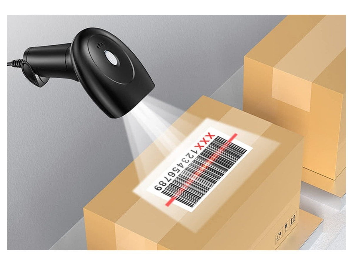
A laser engine sweeps a narrow beam across the code with an oscillating or rotating mirror, and the light that returns lands on a single photodiode. There is no frame and no image anywhere in the chain. What the decoder receives is a one-dimensional waveform, bright and dark in sequence, with the widths of the runs carrying the data.
Two consequences follow directly from that architecture. The first is speed: a waveform can be sampled, thresholded and decoded continuously with very little processing, which is why laser engines hold their read rate as the code moves and why they still turn up on fast sortation lines. The second is that a matrix code cannot be read by this design at all. A QR code carries data in two directions, and the returning signal has one. It is not a firmware restriction that a later update removes.
What the design buys in a warehouse is distance and tolerance of ambient light. The beam is narrow and the receiver can be filtered to its wavelength, so the concentrated spot survives direct sunlight and high-bay lighting that would flatten an imaging sensor. The published advantages of a laser barcode scanner, deeper field and faster continuous reading, come from that same narrow beam rather than from a better decoder.
The price is mechanical. A mirror assembly is a moving part, and a moving part is what fails first after a drop or after a few years of vibration on a forklift. Laser units are also certified to a laser safety class, and the certificate should be part of the specification rather than an assumption: a class 2 unit and a class 1 unit are both legal and are not the same installation.
CCD: the design that brought pixels into barcode reading
A CCD engine uses a linear array of photosensitive cells, lit by a bank of LEDs, and reads a whole row across the code at once instead of sweeping a single point. It removed the moving mirror, and that was the entire point of the design: nothing to wear, nothing to drift out of alignment, no return spring to weaken.
The trade was light and contrast. A CCD array needs the code illuminated evenly and needs a reasonable difference between the bars and the spaces. Across a scuffed label or in bright sunlight the row of pixels either saturates or flattens, and the decode fails in conditions where a laser would have kept working. Depth of field is short for the same reason: the array is fixed and the illumination falls away quickly, so the code has to be presented inside a narrow band.
For a new design, CCD is largely a legacy choice. It survives in low-cost fixed-mount readers and in kiosk modules where the code arrives at a known distance under controlled light, which is exactly the situation the array was built for. When a quotation offers CCD at a price no imager matches, the two questions to ask are the working distance and the light level at the point of use, because those are the two numbers the saving is taken out of.
1D imager: a row of pixels where the mirror used to be
A 1D imager is a linear sensor behind a lens. It captures a stripe across the code, decodes the same symbologies a laser does, and has no moving parts. On paper it competes directly with laser. In the field the difference shows up in failure modes rather than in capabilities, and the failure modes are what a five-year decision actually rests on.
| What changes | Laser | 1D imager |
|---|---|---|
| Moving parts | Mirror assembly and its drive | None |
| Drop and vibration | Mirror alignment is a wear item | Sensor is fixed to the board |
| Reading a phone screen | Poor, because a screen returns very little light to a narrow receiver | Works, because the sensor integrates the emission |
| Long range for the same optics | Reaches further | Usually shorter |
| Damaged or low-contrast labels | Struggles across a tear or a scuff | Reads better, because the signal is sampled and processed |
| Unit cost at equal range | Lower | Slightly higher |
For a counter reader that never leaves the desk the two are interchangeable in daily use, and the cheaper one is the reasonable order. For a device that gets dropped, or that has to read a loyalty code from a customer's phone, the imager is the safer specification, and the difference in unit cost is smaller than one returned unit. The buying decision itself, including the cost of ownership comparison over five years, belongs to a different question and is worked through in 1D versus 2D barcode scanners.
2D imager: capture the frame, then find the code
A 2D imager exposes an area of the scene, thousands of pixels at a time, and hands the whole frame to a decoder that first has to find the code. That search is the part buyers never see and the part that makes the category work. The decoder looks for the finder patterns, works out the perspective the label is being viewed at, resamples the region into a square grid of modules, and only then reads the data out.
Three capabilities fall out of that sequence. A code no longer has to be lined up, because perspective is corrected rather than avoided. Matrix symbologies become readable, because a grid of modules is exactly what the decoder reconstructs. And a damaged label often still reads, because the error correction built into the symbology becomes usable once the module grid is known: a laser crossing a tear loses everything after the tear, while an imager that located the code can reconstruct around a missing corner.
The cost is processing and pixels. Everything that makes a 2D imager flexible depends on putting enough pixels on the code to resolve each module and having a fast enough path to rectify the frame before the operator moves the label. That is why two readers carrying the same three words on the box can behave like different classes of device, and why the numbers below matter more than the label.
Two units with the same sensor and twice the range
Here is the measurement that settles most arguments about engine types. Three of our handhelds carry the same 640 x 480 CMOS sensor. Their published decode ranges, on the same three symbologies, look like this.
| Model | UPC, 13 mil | Code 39, 20 mil | QR code, 20 mil |
|---|---|---|---|
| SN-HM410 | 40 to 130 mm | 70 to 200 mm | 30 to 140 mm |
| SN-HM330 | 30 to 260 mm | 60 to 420 mm | 10 to 200 mm |
| SN-HM930 | 30 to 220 mm | 70 to 330 mm | 30 to 180 mm |
The sensor is identical in all three. The far limit on a UPC label is 130 mm on one and 260 mm on another. Nothing in the phrase 2D imager predicted a factor of two, and no amount of reading the box would have produced it.
The difference is the lens. Focal length, aperture and the point the optics are focused at decide where the code falls inside the sharp band, and the sensor only decides how much of it can be resolved once it is there. A short-focus engine is sharp close up and runs out of focus early, which is what a counter reader needs. A longer focus trades the near range for reach, which is what a stockroom rack needs.
The quality numbers move independently of the range, which is the second half of the same lesson.
| Model | Minimum resolution | Print contrast | Motion tolerance |
|---|---|---|---|
| SN-HM410 | Code 39 at 5 mil | 25 percent | 2.0 m/s |
| SN-HM330 | Code 39 at 4 mil | 35 percent | 2.0 m/s |
| SN-HM930 | Code 39 at 5 mil | 25 percent | 2.5 m/s |
The model that resolves the finest element also demands the most contrast, and that pairing is not an accident: a smaller module puts less light and fewer photons into each element, so the print has to be cleaner for the same read. A buyer who reads only the 4 mil line and orders that unit for a warehouse of worn labels has read half of the specification. Both numbers travel together, and so does the near limit, which matters more than most people expect when the reader has to scan through a glass panel or across a counter edge.
What resolution buys, in pixels per module
Resolution is quoted in mils on a scanner datasheet and in pixels on a sensor datasheet, and the two meet at the module, the narrowest printed element of the code. A mil is one thousandth of an inch: 5 mil is 0.127 mm, and 13 mil, the usual module width of a UPC barcode, is 0.33 mm.
A workable rule of thumb for a 2D code is three pixels across the narrowest module, which leaves the decoder enough signal to threshold reliably under imperfect light. From there the arithmetic is plain, and it is the only arithmetic in this article that a buyer needs to do.
| Sensor width | Modules across a frame at 3 pixels each | Widest 13 mil code (0.33 mm) | Widest 5 mil code (0.127 mm) |
|---|---|---|---|
| 1280 pixels | 426 | 141 mm | 54 mm |
| 640 pixels | 213 | 70 mm | 27 mm |
Read the two rows as a statement about code size rather than about distance. A 1280-pixel sensor can hold a 141 mm wide UPC code in one frame; a 640-pixel sensor holds 70 mm of the same code and has to be closer for the code to fill the frame. The table says nothing about whether the reader focuses at that distance, because the lens decides that, and nothing about reaching twice as far, because doubling the pixel count doubles the code width the frame can hold while leaving the field of view where it was.
Our units are specified with a 640 x 480 or a 1280 x 800 global-shutter CMOS sensor, and both figures are published rather than generalised. The barcode technology page lists the sensor, the aimer and the illumination together, which is the combination that has to be read as one decision.
Global shutter, rolling shutter, and a label that keeps moving
Almost every CMOS sensor can be built to expose either all of its pixels at once or one row at a time. A global shutter exposes the whole array for the same instant. A rolling shutter walks down the array, exposing and reading rows in sequence, which is cheaper to build and fine for a still subject.
Put a moving label in front of a rolling shutter and the frame is a record of different moments: the top rows were captured earlier than the bottom rows, so a code moving horizontally is sheared and one moving vertically is stretched. Within limits the decoder still copes, because it is rectifying the grid anyway. Past those limits it starts returning wrong characters rather than returning nothing, and a wrong character that scans cleanly is worse than a failed read, because nobody notices it until the stock count is wrong.
That is why the shutter type belongs in the specification of anything that reads on a conveyor, a moving pallet or a passing cart. Our handhelds use global-shutter sensors and publish motion tolerance of 2.0 m/s on two models and 2.5 m/s on the third, a figure that is far more useful than the engine type because it can be compared against the actual line speed.
The aimer and the illumination are not the reader
Two lights sit on the front of an imaging scanner and they do different jobs. A red aimer at 617 nm draws the line, cross or frame that the operator lines up with the code. White illumination lights the code so the sensor has something to expose. Neither one decodes anything, and confusing them is how people end up judging a reader by how bright the dot looks.
On an imaging engine the aimer is a promise about the field of view: where the pattern lands is roughly where the sensor is looking, which is why the pattern shape changes between a linear engine and an area engine. On a laser engine there is only one light, because the beam that reads is also the beam the operator sees.
White illumination is what makes a difference on two specific jobs. A phone screen emits its own light, so illumination adds little and can even wash the code out, while the aimer does the work of positioning. A thermal label printed at low contrast is the opposite case: it needs the light, and it needs the print contrast figure from the datasheet to go with it. If either of those jobs is in scope, the illumination specification deserves the same attention as the sensor.
The five spec lines that decide a project
None of the five is the engine type. All five appear on a datasheet that quotes a type, and any one of them can sink a rollout on its own.
| Line | What it actually means | What a weak answer sounds like |
|---|---|---|
| Minimum resolution | The narrowest element the engine can resolve, with the symbology stated | High resolution, without a mil figure |
| Print contrast | The lightest print the engine still reads, as a percentage | Works with all labels |
| Depth of field, per symbology | The near and far limit for each code type and size | One reading distance for the whole range |
| Motion tolerance | The speed at which the code can move and still decode | Not stated, or stated only for a still label |
| Sealing and drop rating | IP number plus the drop height and count that were tested | Rugged, industrial grade |
The pattern in the right-hand column is worth recognizing. Every weak answer replaces a number with an adjective, and adjectives cannot be compared between two quotations. A supplier who cannot state the depth of field for a 13 mil UPC label has not tested the unit on one.
How to write the engine into an RFQ
The engine does not need to be specified by name. It needs to be specified by the job, and five lines do that better than any technology label.
- The symbologies in use today, and the ones expected in two years. Include any matrix code, any code read from a screen, and any code printed in house at a size you control.
- The smallest element and the distance it will be read from. One sentence per code type: a 5 mil element at 80 mm and a 20 mil element at 400 mm are two different requirements and often two different models.
- The speed the code travels. Zero for a counter, the line speed for a conveyor. It sets the shutter and the processing budget.
- The interface and the cable run. USB, serial or keyboard emulation, the host operating system, and the length of cable the installation actually needs.
- The environment. Dust, washdown, sunlight through a window, and the drop height the device will see. This is where IP and drop ratings stop being marketing and start being warranty.
With those five lines written down, the engine type becomes an outcome rather than an input, and a supplier can be held to a band instead of a name. Our own scanner line is a single technology, a 2D imager, chosen because it covers matrix codes, screen codes and damaged labels in one device; the ranges differ by model rather than by technology, which is the point the tables above were making. The barcode scanner range lists them side by side, and the buying guide covers the choices that sit around the engine: form factor, interface and mounting.
Frequently asked questions
Which scan engine type is the best choice?
For a retail or warehouse catalog that contains any matrix code, any phone screen or any label that might arrive damaged, a 2D imager is the only type that covers all three, which is why every scanner we build uses one. A laser engine remains the better tool in one narrow case: a closed operation where every code is a 1D barcode, the labels are printed in house, and the reading happens at a distance. Choosing an engine means matching it to the codes in front of it, not to its position on a timeline from old to new.
Can a laser scanner read a QR code?
No, and no firmware update changes that. A laser engine sweeps a single beam and the receiver sees a one-dimensional waveform of bright and dark widths. A QR code carries data in two directions at once, so one row of it contains a fragment of the message rather than the message. The limit is in the physics of the signal, not in the decoder software.
What does 2D imager actually mean on a datasheet?
It describes the capture geometry: an area sensor reads a full frame and the decoder locates the code inside that frame. It says nothing about working distance, sensor resolution, shutter type or contrast tolerance. Two readers both described as 2D imagers can differ by a factor of two in the distance at which they read the same label, because the lens and the focus point set that band and the label on the box does not mention either.
Is CCD still worth specifying?
Rarely for a new design. A CCD engine brought pixels into barcode reading and removed the moving mirror, but it needs even illumination and good print contrast, and its depth of field is short. It survives where the code is presented at a fixed distance under controlled light, such as a low-cost kiosk module, and where the price difference against an imager is the deciding factor. Ask for the working distance and the light level before accepting the lower price.
What is a mil, and why is 5 mil better than 10 mil?
A mil is one thousandth of an inch, so 5 mil is 0.127 mm and 13 mil, the usual module width of a UPC barcode, is 0.33 mm. A smaller minimum resolution means the engine can resolve finer elements, which matters for small parts, pharmaceutical cartons and dense matrix codes. It is not automatically better: the finer the element, the more print contrast and light the reader needs, which is why one model in our range resolves 4 mil but demands 35 percent print contrast while another resolves 5 mil at 25 percent.
Why do two scanners with the same sensor read at different distances?
Because the lens, not the sensor, decides where the sharp band sits. Three of our handhelds carry the same 640 x 480 CMOS sensor, and their far limit on a UPC label runs from 130 mm to 260 mm. The sensor decides how much of the code can be resolved once it is in focus; the focal length and the focus point decide whether it is in focus at the distance you actually work at. That is why a datasheet that lists one reading distance for a whole family should be read as marketing.